
msrx-usa.com
msrx-usa.com
The Corrective Action Mechanism (CAM) rear takedown pin takes advantage of the mil-spec tolerances of the lower receiver and rear takedown pin, as well as the oval shape of the hole in the upper receiver lug. By pressing the specified degree of bend in a custom CNC milled rear takedown pin, we are able to compensate for out of spec upper receiver lug alignments. Just close the upper on the lower and push the CAM in as if it were a typical rear takedown pin, then rotate it 90° to lock it down.
The CAM rear takedown pin acts as a typical mil-spec pin until rotated, so you can pin any upper onto any CAM equipped lower.
The hole in the rear lug of the typical AR upper receiver is the same height as the diameter of the rear takedown pin holes of the lower receiver, as is indicated at .250"
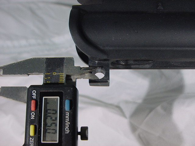
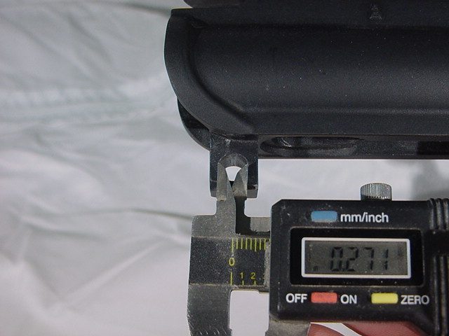
However, the hole in the rear lug of AR upper receivers is oval, rather than round. This is done to allow tolerance so that uppers and lowers from different manufacturers can be mated. This also allows room for the CAM to operate.
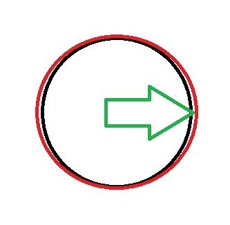
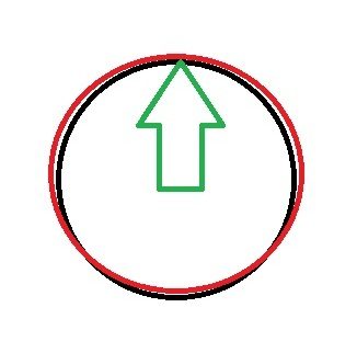
To address loose fitments, the bend of the .002" through .008" compensation CAM rear takedown pin is oriented as indicated by the green arrow when upper and lower are adjoined and the rear takedown pin is initially seated. The black circle of the diagram indicates the takedown pin hole in the lower receiver. The red oval indicates the hole in the lug of the upper receiver.
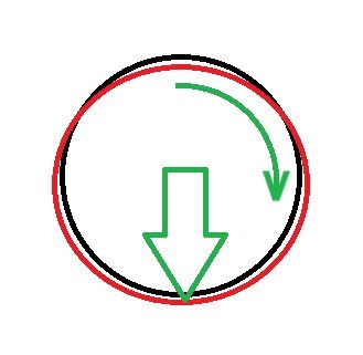
When the CAM is rotated 90 degrees, the bend in the pin forces the lug of the upper receiver downward, clamping it and the lower together. The Corrective Action Mechanism rear takedown pins can compensate for receiver gaps up to .008" wide.
The CAM also offers relief from fitments that are so tight as to require undo force to seat a rear takedown pin. This occurs when the hole in lug of the upper (red oval) doesn't extend far enough into the lower to line up with the holes in the lower (black circle) as shown. The #0 (zero) CAM pin has an upward bend when initially seated, as indicated by the green arrow, allowing it to arc over the bottom of the out of spec hole in the rear lug of the upper and easily pass through the hole in the opposite side of the lower. No hammer required!
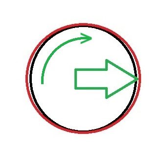
When the #0 CAM pin is rotated 90° after being seated, the upper and lower receivers are drawn back together and locked down. If you have other uppers that share the same lower receiver that do not fit as tight, no worries, the #0 rear takedown pin acts like a typical mil-spec pin when rotated to this position.
To make it possible for the Corrective Action Mechanism takedown pin to function, the detent channel is continued at a 90° angle for one quarter of a revolution, at the end of which a third divot is placed to capture the detent.
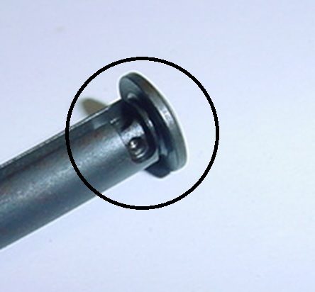
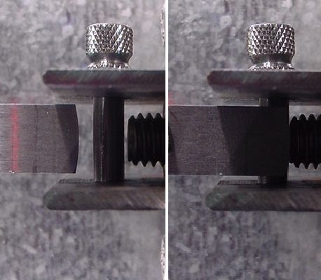
After the detent channel has been milled, each CAM rear takedown pin is placed in the hydraulic press, where the specified amount of correction is applied. Once done, the end of each pin is marked with the amount of correction (in thousandths of an inch) for easy identification. Each pin is then hardened and parkerized for durability.
It doesn't take much to get the job done. This is a finished #8 CAM pin, which will tighten an AR upper/lower receiver gap of up to .008" wide, which is the maximum amount of correction available.

We need your consent to load the translations
We use a third-party service to translate the website content that may collect data about your activity. Please review the details in the privacy policy and accept the service to view the translations.